
Friday, November 19, 2010
Controlled Area Network Board


Can Low means that base voltage (2.2 Volts) is being pulled down from the base voltage when the system is communicating ... the base voltage was being pulled down by 1.5 Volts.
2.2-1.5= 0.7 Volts when communicating and 2.2 Volts when not switched.
Can high means that the base voltage (2.2 Volts) is being pulled up from the base voltage when the system is communicating ... The base voltage is being pulled up by 1.5 Volts.
2.2+1.5= 3.7 Volts when communicating and 2.2 Volts when not switched.
These two are mirror images of each other and is used to double check each message and to make sure there are no wrong messages is transmitted and to identify if there are any faults within the Can system.
.


Both voltage regulators are similar to the voltage regulator we made in TTEC4824 they change the voltage from 12 volt supply to 5 volts
Pin 1 and 2 input U2 7805 Pin 14 VDD
U1 7805 IC chip MCP 2505 - 14 pin
Input 4 and 5 IC UC 5350N Input pin 7-8 in and out of 1-4 goes into IC MCP2505 , Input 12-13 pinout 1 goes to IC2 then to transistor U3 and output is connector 1
For the voltage regulator U1 it is connected to pin 1 (MCRL/VPP) , pin 20 on the positive of the IC chip 18F258 then to LED 1 , then Pin 3 of VCC of the IC4 UC5350N to Pin 15 VSS and Pin 6 is negative which is the ground for IC 3 MAx 232.
For the voltage regulator U1 it is connected to pin 1 (MCRL/VPP) , pin 20 on the positive of the IC chip 18F258 then to LED 1 , then Pin 3 of VCC of the IC4 UC5350N to Pin 15 VSS and Pin 6 is negative which is the ground for IC 3 MAx 232.
For the right indicator the output pin is pin number 5 and the input pin which is on connector 4 and pin number 7 and also a transistor is used U7.
For the rear wipers theoutput connector pin number 7 and the input pin which is also on connector 4 and pin number 9 , also the transistor used is U14 and relay RL4B is used.
Electronic transmissions and scan tools
 Using the workshop manual we can identify all of the sensors and actuators related to the Power train control module.
 Below is a picture of the wiring diagram of a power train control module and their related sensors and actuators.
.


 By using the chart above we can make the following statements:
 .
-Shift solenoid 1-2 and 2-3 are on when the vehicle is shifted into drive & starts out in first gear.
-Shift solenoid 1-2 and 2-3 are on when the vehicle is shifted into drive & starts out in first gear.
-Only shift solenoid 2-3 is on when the vehicle automatically shifts into second gear.
-There are no solenoids on when the vehicle automatically shifts into third.
-Only shift solenoid 1-2 is on when vehicle automatically shifts into fourth
.
.
In case of a solenoid malfunction and none of the solenoids can be actuated ,the vehicle can go into 3rd gear and still just drivable so the vehicle can be taken to a garage or a place to be looked at ... the manufacturer decides this by looking at the performance of the engine and which gear would give us enough speed and at the same time enough torque to allow the car to start from the stationary state and at the same time enough speed so the car can be driven on the road or highway if necessary with out causing too much danger to the occupants and other drivers so this gear can change from a car with low performance engine might be 2nd gear and some other cars with a higher performance engine to have this default gear placed on the 3rd or in some cases even 4th gear.
.
Fault codes:
code: 58 Transmission Fluid temperature (TFT) , signal voltage low. Check power train lamp not illuminated .
For testing the ECT sensor ... we can pull the sensor out and test it on a bench and put it in some water and heat the water up to see if the resistance of the sensor changes correctly (they are normaly NTC so the resistance drops as the temperature increase) and also to check the manufacturer specification for the parameters of this sensor to make sure it is working in the correct range.
Also we can check the circuit by checking for voltage drops on the signal wire to see if there are any high resistance in the signal wire, we can also check the signal voltage against the manufacturer spec to see if we are getting the right voltage or to voltage drop the ground and checking to see if the ground side of the circuit doesn't have any high resistance ... we do this by putting negative prob of the voltmeter on a good ground eg . negative post of the battery and other prob on the earth side of the circuit to see if there is significant voltage difference between the two points . In the manufacturer manual states this code can also be the cause of the transmission fluid temperature reaching 182 degree C for 1 second . but there are no default actions taken by the Power train control module.
.
Code: 82 , 1-2 shift solenoid circuit faulty. Check power train lamp is illuminated .
In order for us to get this fault code the PCM has detected an in appropiate voltage on the 1-2 shift solenoid cuircuit for 2 seconds or longer. This will cause the shifts to be firm hard shifts and this is because all the set line pressure is pushed to the maximum . It also could cause the power train to only go in to the 2nd and 3rd or only 1st and 4th. The torque converter clutch also would not be actuted on so it can help with smoothing the ride and having more torque if needed . We can check the supply voltage and because they are normally earth triggered with the ignition on we should have supply voltage to the solenoids which we can check against manufaturer spec , we can also locate a high resistance or open curcuit before the solenoide... an other way we can check this solenoid is to check the earth side of the circuit but pay attention to the situation where we are checking the solenoid and whether it is supposed to be on or not at time of checking ... we can voltage drop the earth to see if the solenoid has good earth or any high resistance or bad connections on the earth circuit . At last and not least we can take the solenoid out and test it on a bench eg. resistance of the winding or to see if there is any earth leaks to the body and even by knowing the voltage from the manufaturer spec we can test the solenoid and not damaging it to see if it is working appropiatly or infact faulty which replacement is an easy option since we have already removed it .
.
Torque converter clutch:
Unfortunatly we couldnt see the Torque converter clutch on our live data on the scan tool so I cant say when exactly it is on or off but from the what I've learned so far can tell you that the torque converter lock up clutch only comes on when the vehicle is in cruise mode and does this to conserve energy when cruising by locking up the torque converter and is disengaged usually by the foot brake pedal switch or when the speed of the vehicle has decreased past and less than the speed set by the manufacturer.
.


Using a scan tool

We first connect the Scan tool to the OBD2 plug under the bonnet.
After correctly following the right steps so we wont damage the vehicle or the scan tool we start the car and after following the right options on the scan tool we correcly identify the vehicle on the scan tool and then under the ABS part we can observe the live data :
Front left wheel speed sensor.
Front right wheel speed sensor.
Rear left wheel speed sensor.
Rear right wheel speed sensor.
Brake light switch.
Automatic stability control switch.
.
By looking at the scan tool we can also go to the actuator test screen and see what actuators we can observe working on the live data :
.
Solenoid valve 1
Solenoid valve 2
solenoid valve 3
ABS wheel speed sensors

The vehicle we were working on has an analogue sensor and we can identify this by looking at number of wires to the sensor ... analogue sensors has 2 wires to it , signal and earth and digital sensors have 3 wires ... supply, signal , earth . we can also tell this by looking at the signal wire of the sensor with a oscilloscope and whether it is digital or analogue .
Front left : 0.05 centimeters
Front right : 0.05 centimeters
Rear left : 0.05 centimeters
Rear right : 0.05 centimeters
All within manufacturer specification and no sign of physical damage to the sensors.
.

By looking at the above pattern we can easily tell that this sensor is an analogue sensor as the output voltage goes positive and negative voltage where digital voltage is normally just positive . By using the frequency scale on a multi-meter we can also note the frequency which is 210 Hz
Each cycle or frequency or revolution is close to 5 mili seconds = 0.0005 seconds.
1 / frequency = time ,so 1 / Time = frequency , 1 / 0.0005 = 200 Hz
On car exercises
On the following page I am going to show various parts of an ABS components and briefly explain where they can be found ...
Wheel speed sensor Can be found on each wheel and depending on their types and manufacture can be found on different part of the wheel assembly. There are different types ... Inductive , Magnetic, hall effect , optical , magnito resistor ...
 ABS control unit can also be found in different positions depending on the manufature .

ABS modulator can be found under the bonnet around the engine or in some cases under the vehicle and at the back arches.
 ABS pump motor can be found next to the ABS modulator .
 Parking brake switch can be found located on the parking brake lever and is located various parts depending on the type of lever used .

Brake master cylinder is located on the firewall and normally on the driver side and infront of the brake booseter.

Brake fluid level switch is normally located on the lid of the reservoir and alerts the driver with a warning dash light when the fluid is low .

RPM sensor is also different in types and located in various part of the engine ... the picture below shows an inductive type of RPM sensor.

Foot brake switch is located by the foot brake pedal and is turned on as soon as the driver foot presses the pedal by a small margin even before the brake has been actuated.

Brake booster is located on the firewall and normally on the driver side .

Main ABS control unit fuse is normally located in the fuse box and normally under the bonnet .

Wheel speed sensor Can be found on each wheel and depending on their types and manufacture can be found on different part of the wheel assembly. There are different types ... Inductive , Magnetic, hall effect , optical , magnito resistor ...
 ABS control unit can also be found in different positions depending on the manufature .
ABS modulator can be found under the bonnet around the engine or in some cases under the vehicle and at the back arches.
 ABS pump motor can be found next to the ABS modulator .
 Parking brake switch can be found located on the parking brake lever and is located various parts depending on the type of lever used .
Brake master cylinder is located on the firewall and normally on the driver side and infront of the brake booseter.

Brake fluid level switch is normally located on the lid of the reservoir and alerts the driver with a warning dash light when the fluid is low .
RPM sensor is also different in types and located in various part of the engine ... the picture below shows an inductive type of RPM sensor.

Foot brake switch is located by the foot brake pedal and is turned on as soon as the driver foot presses the pedal by a small margin even before the brake has been actuated.

Brake booster is located on the firewall and normally on the driver side .

Main ABS control unit fuse is normally located in the fuse box and normally under the bonnet .

On vehicle testing:
The following steps have to be taken to ensure the safty of people working around the car while lefting and supporting a vehicle and also to make sure we don't damage the vehicle while lefting or supproting the vehicle ...
This is very important to follow these steps ...
 The following steps are to be taken when lowering the vehicle for safty and not damaging the vehicle ...

This is very important to follow these steps ...
 The following steps are to be taken when lowering the vehicle for safty and not damaging the vehicle ...
ABS pump relay waveform

ABS Self test:
When we switch the ignition on ... ABS does a selfcheck in order to see whether all the components are working , there is a 12 volts is supplied to the pin number 1H of the ABS control module and also to the fail safe relay , at this point the ABS warning light has a 12 volt supply from the pin number 2L and thru the fail safe relay to ground so the light is on . The ABS control module checks most of the components of the ABS unit except for the parts it can not check like the ABS wheel speed sensors which cannot be checked while the car is stationary.
When the failsafe is switched the ground side of the warning light gets a 12 volt supply voltage which in fact turns of the light as there is no flow of current thru the light. The fail safe ground is on pin 2J which shows this relay is earth triggered so if there is any problems with any of the components or circuit ... the ABS control module doesnt trigger the failsafe relay and the ABS warning light on the dash would stay on ! this will tell the driver that the ABS has found a fault and is not working , also if there is no issues it will be turned off and tell the driver that the ABS is working .
When the failsafe is switched the ground side of the warning light gets a 12 volt supply voltage which in fact turns of the light as there is no flow of current thru the light. The fail safe ground is on pin 2J which shows this relay is earth triggered so if there is any problems with any of the components or circuit ... the ABS control module doesnt trigger the failsafe relay and the ABS warning light on the dash would stay on ! this will tell the driver that the ABS has found a fault and is not working , also if there is no issues it will be turned off and tell the driver that the ABS is working .
Create a fault:
We used a part of a plastic pipe to slow down one of the wheels while we were braking on the ABS demonstrator and the ABS control module picks this up as one of the wheels is slowing down faster than the others or thinks its going to lock up ... ABS control module prevents this from happening by closing the inlet valve via a solenoid on the wheel so there is no more extra pressure is being applied, then if this doesn't speed up the wheel to match the other 3 wheels, it will also open the outlet valve via solenoid to release the pressure on the particular wheel so it can speed back up and not lock up .
ABS Solenoid actuating:
Left front solenoid pin : ....... 1B
Right front solenoid pin : ..... 1C
Left rear solenoid pin: .......... 1D
Right rear solenoid pin : ....... 1A
we can get this info by looking at the ABS demonstrator wiring diagram which i have put the particular part of the diagram under ...

This is the Right rear solenoid pin 1A which has been actuated to either close the inlet valve so the pressure on the wheel slowing down is not increasing so it can match the other wheels or open the outlet valve to release pressure so the wheel wouldn't lock up .

ABS Relays
By looking at the diagram given earlier we can identify the following relays :
Relays or switches that powers up the ABS ECU : Relay K39.
Relays or switches that power ups the ABS pump : Relay K100.
Relays or switches that sends power to the ABS HCU solenoids : Relay K38
The ECU pin number #1 is the wire that brings the power to the ABS ECU.
The ECU pin number #27 is the wire that controls the relay for the ABS ECU.
The ECU pin number #14 is the wire that brings power to the ABS pump.
The ECU pin number # 28 is the wire that controls the relay for the ABS pump.

Channel 1 is the control circuit , and channel 2 is the switching circuit.
This is when the ABS relay does the self check.
At point A is when switching circuit is turned on from 0 Volts to 12 volts .this is because the control circuit has been grounded so it can create a magnetic field to attract the circuit 2 to be turned on .
Point C the control circuit has collapsed on itself and we can see the voltage spike . Point B is where the switch is open and switching circuit now open ..
Point E and D is when the pump has been turned on and then off and we can see the oscilations .
ABS Demonstrators
Here are the ABS wheel speed sensor ECU pinouts :
Left front ..... ECU pin # 2O and 2P
Left rear ...... ECU pin # 2R and 2Q
right front ... ECU pin # 2N and 2M
Right rear ... ECU pin # 2S and 2T
By looking at the wiring diagram we can idenitfy the INDUCTIVE wheel speed sensors.
Because Hall effect or optical types use 3 wires but inductive or magnetic type use only 2 .
As the teeth approaches the sensor due to the magnetic field being crossed gets more opposite and is at the maximum when the teeth is at the closest point to the sensor ... as the teeth starts moving away from the sensor the magnetic field that crosses the sensor slowly disappears and the voltage becomes more negative until the magnetic field is so far that dosnt effect the sesnor at all ...as the speed of the ring teeth increases so does the voltage and frequency, this repeats as the next teeth approaches and the cycle continues. this kind of sensor creates AC waveform .
optical and hall effect type create a digital signal . some magnito resistor sensors can also create a digital signal.
We were using TDS1002 techtonic oscilloscope for the next excercise .
Front Left.

Rear right.

Left front ..... ECU pin # 2O and 2P
Left rear ...... ECU pin # 2R and 2Q
right front ... ECU pin # 2N and 2M
Right rear ... ECU pin # 2S and 2T
By looking at the wiring diagram we can idenitfy the INDUCTIVE wheel speed sensors.
Because Hall effect or optical types use 3 wires but inductive or magnetic type use only 2 .
As the teeth approaches the sensor due to the magnetic field being crossed gets more opposite and is at the maximum when the teeth is at the closest point to the sensor ... as the teeth starts moving away from the sensor the magnetic field that crosses the sensor slowly disappears and the voltage becomes more negative until the magnetic field is so far that dosnt effect the sesnor at all ...as the speed of the ring teeth increases so does the voltage and frequency, this repeats as the next teeth approaches and the cycle continues. this kind of sensor creates AC waveform .
optical and hall effect type create a digital signal . some magnito resistor sensors can also create a digital signal.
We were using TDS1002 techtonic oscilloscope for the next excercise .
Front Left.
 Front Right.
 Rear left.
Rear right.
All the waveforms are not exactly the same due to the difference of the gap between each ring tooth and sensors on each wheel and because they all have different gaps.
These are the wheel speed sensor spinning and their measured AC Voltage with a multi-meter .
Left front: 5.46 Volts
Left rear: 4.21 Volts
Right front: 7.4 Volts
Right rear: 6.23 Volts
A multimeter is not as an accurate tool for finding problems on a wheel speed sensors . An oscilloscope is a very good tool for this task . A multimeter can not show us what exactly is happening to the live data we getting and can only give us the calculated root mean square RMS and unfortunatly can not show us what actualy is going on ... different voltages from different wheel sensors but at the same speed can also be caused by different gap sizes between tooth ring and sensors, magnetic dust on the sensor e.g. from driving on sand or wrong size wheels can also effect the voltage as a bigger wheel would rotate slower ...
Wiring diagram practice
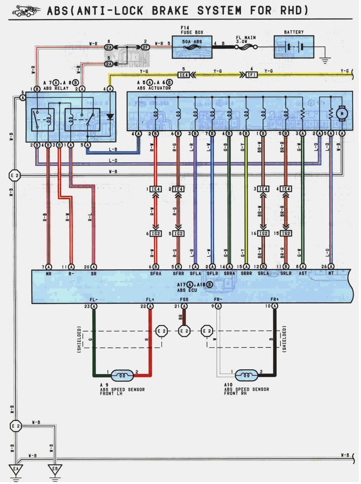
 Front Right speed sensor wires as we can see above are Black and white .
Front left speed sensor wires are Red and Green.

A little bit confusing by looking at the above diagram because there is a printing mistake which is quiet common . I have also pointed this out by arrows in the photo under ... it is quiet easy to figure out though because the wire labels are for Rear of the car and they have label the sensors incorrectly .
Rear right speed sensor wire colours are brown and yellow.
Rear left speed sensor wire colours are pink and blue

ABS speed sensor wires are braided to stop any interference with the sensor signal .
There are 4 different types of fuses are used in a ABS circuit...
Fuseable links 3.0 watts
50 Amps Main ABS fuse
20 Amps Dome
15 Amps Stop
15 Amps ECU
10 Amps Gauge
B7 and B10 are ABS ECU ground wires .
26 L0 is the motor wire.
On the wiring diagram for the ABS actuators , there are solenoids which control each wheel cylinder .
Front right wheel solenoid wire colour : Red-White pin number : 6 APPLY
: Red-Green : 5 RELEASE
Front left wheel solenoid wire colour : Blue-Red pin number : 1 APPLY
: Blue-White : 2 RELEASE
Rear right wheel solenoid wire colour : Green-Black pin number : 14 APPLY
: Green-Yellow : 15 RELEASE
Rear left wheel solenoid wire colour : Brown-White pin number : 12 APPLY
: Brown-Red :11 RELEASE
 Using the picture above as a guide we can give the following statements :
the correct conditions of the inlet and outlet solenoids valves under normal braking are ...
Inlet valve open , Outlet valve closed
The correct conditions of the inlet and outlet valves when the ABS is operating to reduce wheel brake pressure are ...
Inlet valve closed , outlet valve open
The correct conditions of the inlet and outlet valves when the ABS is operating to hold brake pressure are ...
Inlet valve closed , outlet valve closed
The correct conditions of the inlet and outlet valves when the ABS is operating to increase wheel brake pressure are ...
Inlet valve open , outlet valve closed
In the Four cases above the ABS motor and pump is working when the ABS is actuated .

On the graph above I draw a digital signal that switches 5 Volts every 2 seconds .

On the graph above I draw an analogue signal with a frquency of 0.5 Hz and a maximum of +3 volts .
ABS Wiring operation
 1. Disc
2. Speed sensor
3. Tone ring
4. ABS module
5. Master cylinder
6. Caliper
7. Booster
Subscribe to:
Posts (Atom)