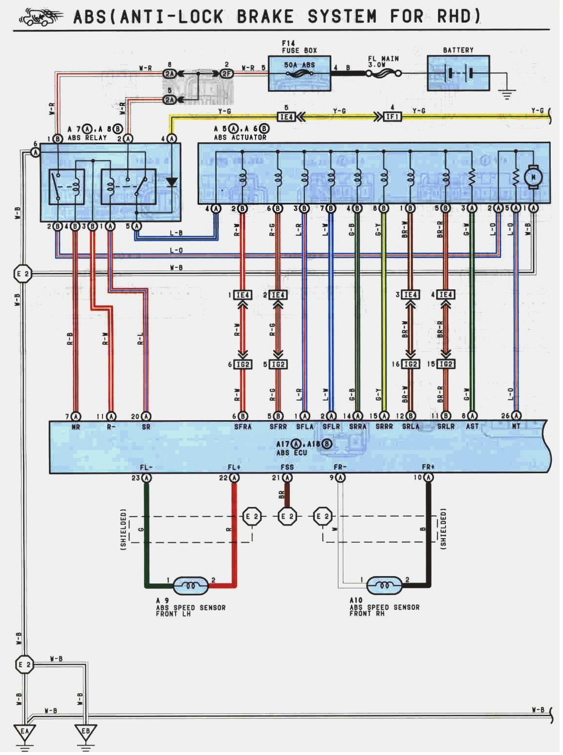
 Front Right speed sensor wires as we can see above are Black and white .
Front left speed sensor wires are Red and Green.

A little bit confusing by looking at the above diagram because there is a printing mistake which is quiet common . I have also pointed this out by arrows in the photo under ... it is quiet easy to figure out though because the wire labels are for Rear of the car and they have label the sensors incorrectly .
Rear right speed sensor wire colours are brown and yellow.
Rear left speed sensor wire colours are pink and blue

ABS speed sensor wires are braided to stop any interference with the sensor signal .
There are 4 different types of fuses are used in a ABS circuit...
Fuseable links 3.0 watts
50 Amps Main ABS fuse
20 Amps Dome
15 Amps Stop
15 Amps ECU
10 Amps Gauge
B7 and B10 are ABS ECU ground wires .
26 L0 is the motor wire.
On the wiring diagram for the ABS actuators , there are solenoids which control each wheel cylinder .
Front right wheel solenoid wire colour : Red-White pin number : 6 APPLY
: Red-Green : 5 RELEASE
Front left wheel solenoid wire colour : Blue-Red pin number : 1 APPLY
: Blue-White : 2 RELEASE
Rear right wheel solenoid wire colour : Green-Black pin number : 14 APPLY
: Green-Yellow : 15 RELEASE
Rear left wheel solenoid wire colour : Brown-White pin number : 12 APPLY
: Brown-Red :11 RELEASE
 Using the picture above as a guide we can give the following statements :
the correct conditions of the inlet and outlet solenoids valves under normal braking are ...
Inlet valve open , Outlet valve closed
The correct conditions of the inlet and outlet valves when the ABS is operating to reduce wheel brake pressure are ...
Inlet valve closed , outlet valve open
The correct conditions of the inlet and outlet valves when the ABS is operating to hold brake pressure are ...
Inlet valve closed , outlet valve closed
The correct conditions of the inlet and outlet valves when the ABS is operating to increase wheel brake pressure are ...
Inlet valve open , outlet valve closed
In the Four cases above the ABS motor and pump is working when the ABS is actuated .

On the graph above I draw a digital signal that switches 5 Volts every 2 seconds .

On the graph above I draw an analogue signal with a frquency of 0.5 Hz and a maximum of +3 volts .
No comments:
Post a Comment